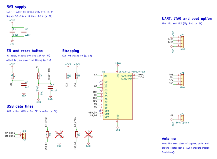
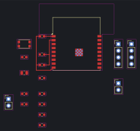
| U1 | ESP32-C3-WROOM-02 | RF_Module:ESP32-C3-WROOM-02 | RF_Module:ESP32-C3-WROOM-02 | Espressif Systems, p. 34, Figure 9-1 Peripheral Schematics; pin table p. 11 |
| C1 | 10uF | Device:C | Capacitor_SMD:C_0805_2012Metric | Espressif Systems, p. 34, Figure 9-1, C1 on VDD33 |
| C2 | 0.1uF | Device:C | Capacitor_SMD:C_0603_1608Metric | Espressif Systems, p. 34, Figure 9-1, C2 on VDD33 |
| R1 | 10k | Device:R | Resistor_SMD:R_0603_1608Metric | Espressif Systems, p. 34, Figure 9-1 R1 (value TBD there); note: RC delay at EN, usually R = 10 kOhm |
| C3 | 1uF | Device:C | Capacitor_SMD:C_0603_1608Metric | Espressif Systems, p. 34, Figure 9-1 C3 (value TBD there); note: RC delay at EN, usually C = 1 uF |
| R2 | 0 | Device:R | Resistor_SMD:R_0603_1608Metric | Espressif Systems, p. 34, Figure 9-1, R2 in series with the reset switch |
| SW1 | RESET | Switch:SW_Push | Button_Switch_SMD:SW_Push_1P1T_NO_CK_KMR2 | Espressif Systems, p. 34, Figure 9-1, SW1 |
| C4 | 0.1uF | Device:C | Capacitor_SMD:C_0603_1608Metric | Espressif Systems, p. 34, Figure 9-1, C4 across the reset switch |
| R9 | 10k | Device:R | Resistor_SMD:R_0603_1608Metric | Espressif Systems, p. 34, Figure 9-1, R9 pull-up on IO2 |
| R8 | 10k | Device:R | Resistor_SMD:R_0603_1608Metric | Espressif Systems, p. 34, Figure 9-1, R8 pull-up on IO8 |
| JP3 | USB | Connector_Generic:Conn_01x02 | Connector_PinHeader_2.54mm:PinHeader_1x02_P2.54mm_Vertical | Espressif Systems, p. 34, Figure 9-1, JP3 USB (pin 1 USB_D+, pin 2 USB_D-) |
| R6 | 0 | Device:R | Resistor_SMD:R_0603_1608Metric | Espressif Systems, p. 34, Figure 9-1, R6 in series with USB_D- |
| C6 | TBD not fitted | Device:C | Capacitor_SMD:C_0603_1608Metric | Espressif Systems, p. 34, Figure 9-1, C6 (TBD, not fitted) |
| R4 | 0 | Device:R | Resistor_SMD:R_0603_1608Metric | Espressif Systems, p. 34, Figure 9-1, R4 in series with USB_D+ |
| C5 | TBD not fitted | Device:C | Capacitor_SMD:C_0603_1608Metric | Espressif Systems, p. 34, Figure 9-1, C5 (TBD, not fitted) |
| JP4 | UART | Connector_Generic:Conn_01x04 | Connector_PinHeader_2.54mm:PinHeader_1x04_P2.54mm_Vertical | Espressif Systems, p. 34, Figure 9-1, JP4 UART (VDD33, TXD, RXD, GND) |
| JP1 | JTAG | Connector_Generic:Conn_01x04 | Connector_PinHeader_2.54mm:PinHeader_1x04_P2.54mm_Vertical | Espressif Systems, p. 34, Figure 9-1, JP1 JTAG; pin functions p. 11 (IO4 MTMS, IO5 MTDI, IO6 MTCK, IO7 MTDO) |
| JP2 | Boot Option | Connector_Generic:Conn_01x02 | Connector_PinHeader_2.54mm:PinHeader_1x02_P2.54mm_Vertical | Espressif Systems, p. 34, Figure 9-1, JP2 Boot Option (IO9 to GND) |