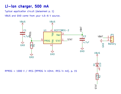
MCP73831-2 single-cell Li-ion/Li-polymer charger with the typical application circuit from Microchip's datasheet: 4.7 µF input and output capacitors, 2 kΩ programming resistor for 500 mA, and a status LED.
DraftPower7 partsApache-2.0
Draft. Nobody has checked this against the datasheet yet. It follows MCP73831/2 Miniature Single-Cell, Fully Integrated Li-Ion, Li-Polymer Charge Management Controllers, DS20001984H, KiCad opens it without errors, and the nets match the specification. Check the values yourself before you build it.
The schematic as KiCad draws it. Open it at full size to zoom: it is a vector image.
Pins used on MCP73831-2
Pin numbers follow the datasheet's pin table. Every other pin is marked no-connect (X), so you can see what is free; delete the marker to use a pin.
Pin
Name in KiCad
Net
1
STAT
STAT
2
V_{SS}
GND
3
V_{BAT}
VBAT
4
V_{DD}
VBUS
5
PROG
PROG
Checklist
Required
Supply (VDD) must be 3.75 to 6 V, and the datasheet recommends VREG + 0.3 V up to 6 V: 4.5 V or more for this 4.20 V part. The absolute maximum is 7.0 V. (Microchip Technology, p. 11, Sec. 3.1; DC characteristics and Absolute Maximum Ratings, p. 3)
This is the -2 option: it charges to 4.20 V (+/-0.75%). Use it only with cells that charge to 4.20 V. The -3, -4 and -5 options regulate to 4.35, 4.40 and 4.50 V. (Microchip Technology, p. 3, Voltage regulation, VREG)
Set the charge current with RPROG: IREG (mA) = 1000 / RPROG (kOhm). 2 kOhm gives 500 mA. RPROG must be 2 to 67 kOhm, and the datasheet prefers a 1C charge rate, so 500 mA suits a cell of about 500 mAh or more. (Microchip Technology, p. 15, Sec. 5.1.2; RPROG range p. 4; Sec. 6.1.1.1 p. 17)
Fit at least 4.7 uF from VDD to ground and at least 4.7 uF from VBAT to ground. The VBAT capacitor keeps the loop stable when the battery is disconnected. (Microchip Technology, p. 11, Secs. 3.1 and 3.2)
This is a linear charger, so the voltage drop is dissipated as heat. From 5 V into a 3.6 V cell at 500 mA that is about 0.7 W. The SOT-23-5 package is rated 230 C/W (4-layer test board), so the chip would overheat; it then lowers the charge current by thermal regulation. Expect slower charging on a small board, and give the package copper. (Microchip Technology, p. 5, Thermal resistance, p. 5; thermal regulation, p. 1 (the power is calculated here))
Recommended
If the input is hot-pluggable, as a USB cable is, add input overvoltage protection: the datasheet suggests a transient suppressor from the supply connector to ground. (Microchip Technology, p. 18, Sec. 6.1.1.2)
The charger does not protect the cell from over-discharge or a short circuit. Use a cell with a protection circuit, or add one. (common practice)
Good to know
STAT is low while charging, high when charging is complete and high impedance when there is no battery or the charger is shut down (MCP73831). The LED between VBUS and STAT through 470 ohm lights while charging. STAT can also drive a microcontroller input. (Microchip Technology, p. 15, Table 5-1; Sec. 3.3 p. 11)
Letting PROG float, or driving it high, disables the charger and ends the charge cycle. A switch or transistor on PROG can inhibit charging. (Microchip Technology, p. 18, Sec. 6.1.1.6)
PCB layout
7 footprints, 13 tracks and 4 vias, drawn for KiCad and checked with its design rule check and schematic comparison. The block has no board outline: it takes the one of the board you place it on.
The layout as KiCad draws it: front copper red, back copper blue.
Keep the 4.7 uF input and battery capacitors within a few millimetres of the VBUS and VBAT pins, with a short return to ground. (common practice)
Put the PROG resistor right at pin 5 and keep stray capacitance off that node: it sets the charge current. (common practice)
The status LED loop is long on purpose, so the block stays in one row; move the LED next to the pins when you place it. Ground returns on the back layer; the block takes the board outline and ground pour of the project. (common practice)
Parts list
Ref
Value
KiCad symbol
Footprint
Source
U1
MCP73831-2
Battery_Management:MCP73831-2-OT
Package_TO_SOT_SMD:SOT-23-5
Microchip Technology, p. 1, Typical Application; pin functions Table 3-1, p. 11
C1
4.7uF
Device:C
Capacitor_SMD:C_0805_2012Metric
Microchip Technology, p. 1, Typical Application; minimum 4.7 uF on VDD, Sec. 3.1 p. 11
C2
4.7uF
Device:C
Capacitor_SMD:C_0805_2012Metric
Microchip Technology, p. 1, Typical Application; minimum 4.7 uF on VBAT, Sec. 3.2 p. 11
R1
2k
Device:R
Resistor_SMD:R_0603_1608Metric
Microchip Technology, p. 1, Typical Application; IREG = 1000 V / RPROG, p. 15
R2
470
Device:R
Resistor_SMD:R_0603_1608Metric
Microchip Technology, p. 1, Typical Application, status LED resistor
D1
LED
Device:LED
LED_SMD:LED_0603_1608Metric
Microchip Technology, p. 1, Typical Application, status LED
In KiCad 9 or later. Unzip the download. Open Preferences › Manage Design Block Libraries, add the unzipped crossprobe.kicad_blocks folder as a library, then place the block from the design block chooser. The symbols and footprints are KiCad's own.
In Crossprobe. Choose Open in Crossprobe above. It opens a new project with this block already in its schematic, using the reference designators from the table above. The project stays in your browser until you save it, and you pick where it goes. To add the block to a project you already have, open that project, turn on Edit and use Add block.