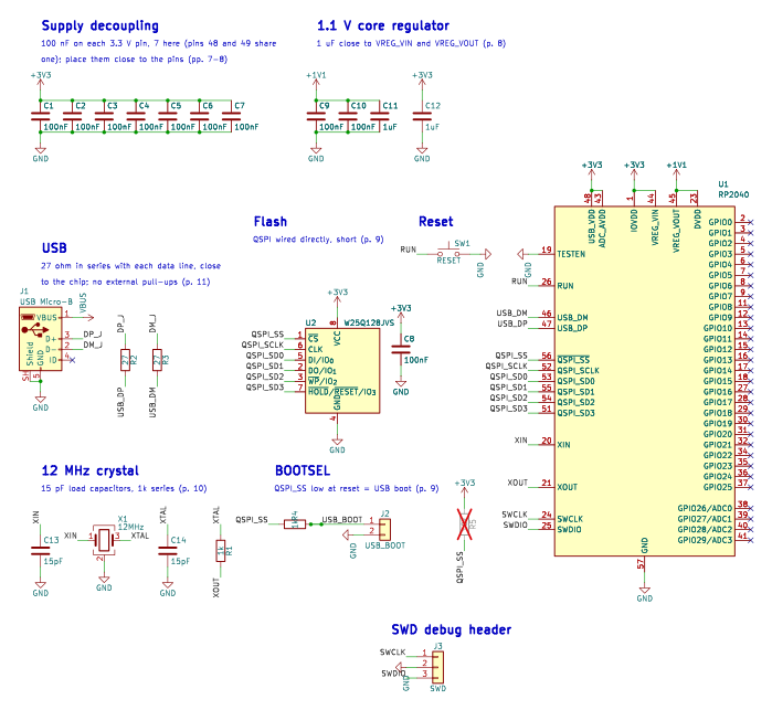
| U1 | RP2040 | MCU_RaspberryPi:RP2040 | Package_DFN_QFN:QFN-56-1EP_7x7mm_P0.4mm_EP3.2x3.2mm | Raspberry Pi Ltd, p. 13, Figure 11, complete schematic |
| C1 | 100nF | Device:C | Capacitor_SMD:C_0402_1005Metric | Raspberry Pi Ltd, p. 7, one 100 nF per 3.3 V supply pin; pins 48 and 49 share one (pp. 7-8) |
| C2 | 100nF | Device:C | Capacitor_SMD:C_0402_1005Metric | Raspberry Pi Ltd, p. 7, one 100 nF per 3.3 V supply pin; pins 48 and 49 share one (pp. 7-8) |
| C3 | 100nF | Device:C | Capacitor_SMD:C_0402_1005Metric | Raspberry Pi Ltd, p. 7, one 100 nF per 3.3 V supply pin; pins 48 and 49 share one (pp. 7-8) |
| C4 | 100nF | Device:C | Capacitor_SMD:C_0402_1005Metric | Raspberry Pi Ltd, p. 7, one 100 nF per 3.3 V supply pin; pins 48 and 49 share one (pp. 7-8) |
| C5 | 100nF | Device:C | Capacitor_SMD:C_0402_1005Metric | Raspberry Pi Ltd, p. 7, one 100 nF per 3.3 V supply pin; pins 48 and 49 share one (pp. 7-8) |
| C6 | 100nF | Device:C | Capacitor_SMD:C_0402_1005Metric | Raspberry Pi Ltd, p. 7, one 100 nF per 3.3 V supply pin; pins 48 and 49 share one (pp. 7-8) |
| C7 | 100nF | Device:C | Capacitor_SMD:C_0402_1005Metric | Raspberry Pi Ltd, p. 7, one 100 nF per 3.3 V supply pin; pins 48 and 49 share one (pp. 7-8) |
| C8 | 100nF | Device:C | Capacitor_SMD:C_0402_1005Metric | Raspberry Pi Ltd, p. 8, flash supply decoupling, Figure 7 (p. 8) |
| C9 | 100nF | Device:C | Capacitor_SMD:C_0402_1005Metric | Raspberry Pi Ltd, p. 7, DVDD decoupling (p. 7; design files) |
| C10 | 100nF | Device:C | Capacitor_SMD:C_0402_1005Metric | Raspberry Pi Ltd, p. 7, DVDD decoupling (p. 7; design files) |
| C11 | 1uF | Device:C | Capacitor_SMD:C_0402_1005Metric | Raspberry Pi Ltd, p. 8, 1 uF close to VREG_VOUT (p. 8) |
| C12 | 1uF | Device:C | Capacitor_SMD:C_0402_1005Metric | Raspberry Pi Ltd, p. 8, 1 uF close to VREG_VIN (p. 8) |
| U2 | W25Q128JVS | Memory_Flash:W25Q128JVS | Package_SO:SOIC-8_5.3x5.3mm_P1.27mm | Raspberry Pi Ltd, p. 9, Flash storage, Figure 7 |
| X1 | 12MHz | Device:Crystal_GND24 | Crystal:Crystal_SMD_3225-4Pin_3.2x2.5mm | Raspberry Pi Ltd, p. 10, Crystal oscillator, Figure 8; Table 1 |
| C13 | 15pF | Device:C | Capacitor_SMD:C_0402_1005Metric | Raspberry Pi Ltd, p. 10, load capacitors C2 and C3, Figure 8 |
| C14 | 15pF | Device:C | Capacitor_SMD:C_0402_1005Metric | Raspberry Pi Ltd, p. 10, load capacitors C2 and C3, Figure 8 |
| R1 | 1k | Device:R | Resistor_SMD:R_0402_1005Metric | Raspberry Pi Ltd, p. 10, series resistor R5, Figure 8 |
| J1 | USB Micro-B | Connector:USB_B_Micro | Connector_USB:USB_Micro-B_Amphenol_10103594-0001LF_Horizontal | Raspberry Pi Ltd, p. 7, Input supply: J1 Micro-USB, Figure 4 |
| R2 | 27 | Device:R | Resistor_SMD:R_0402_1005Metric | Raspberry Pi Ltd, p. 11, series termination R3, Figure 9 |
| R3 | 27 | Device:R | Resistor_SMD:R_0402_1005Metric | Raspberry Pi Ltd, p. 11, series termination R4, Figure 9 |
| R4 | 1k | Device:R | Resistor_SMD:R_0402_1005Metric | Raspberry Pi Ltd, p. 9, USB_BOOT circuit R1, Figure 7 |
| J2 | USB_BOOT | Connector_Generic:Conn_01x02 | Connector_PinHeader_2.54mm:PinHeader_1x02_P2.54mm_Vertical | Raspberry Pi Ltd, p. 9, USB_BOOT header J2, Figure 7 |
| R5 | 10k not fitted | Device:R | Resistor_SMD:R_0402_1005Metric | Raspberry Pi Ltd, p. 9, pull-up R2, marked DNF, Figure 7 |
| SW1 | RESET | Switch:SW_Push | Button_Switch_SMD:SW_Push_1P1T_NO_CK_KMR2 | Raspberry Pi Ltd, p. 9, restarting by toggling RUN |
| J3 | SWD | Connector_Generic:Conn_01x03 | Connector_PinHeader_2.54mm:PinHeader_1x03_P2.54mm_Vertical | common practice |